
After reffing at my fair share of VEX tournaments in recent years, I’ve come to determine that I’m really not a fan of the web interface that is used to start/stop the match timers. Holding a phone or tablet like that in my hand for a long period of time is very bothersome to me and I wanted to design a better solution that would make the experience more bearable :3
It’s a fairly simple device, and could actually be easily reconfigured to do just about anything, not just control VEX matches. It uses an ESP8266 microcontroller that I programmed using C++.
I first designed the shell using Autodesk Inventor, my CAD software of choice. I was recently gifted a 3D printer and decided to make good use of it. This contraption had four main parts.
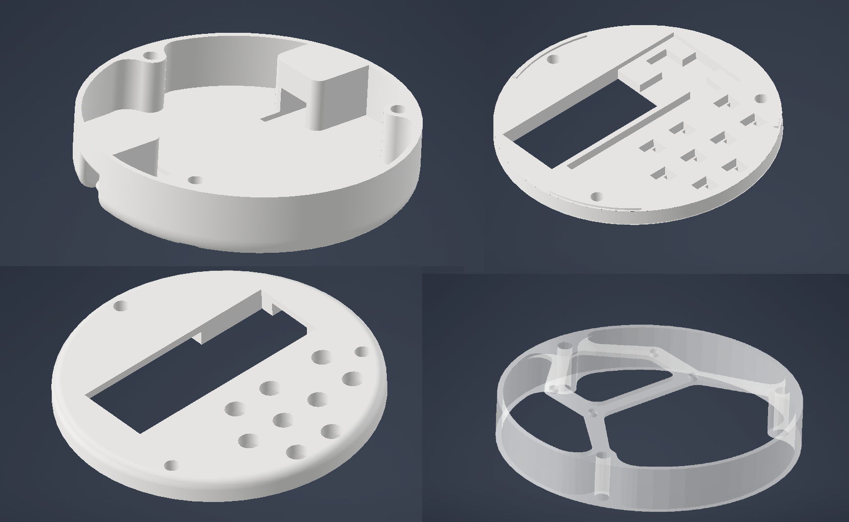
There were the front and back casing layers, as well as two spacing layers in between. One contained the buttons, and the other was for mounting the electronics and containing the wiring.
It took a couple of iterations to get some of this stuff right. For example, I had a few failed prototypes for the layer that holds the LCD because I forgot to account for some ridges on the backside. The electronics layer is intentionally made out of a translucent material, as opposed to the other layers which are opaque, to allow the lighting effects to work properly.
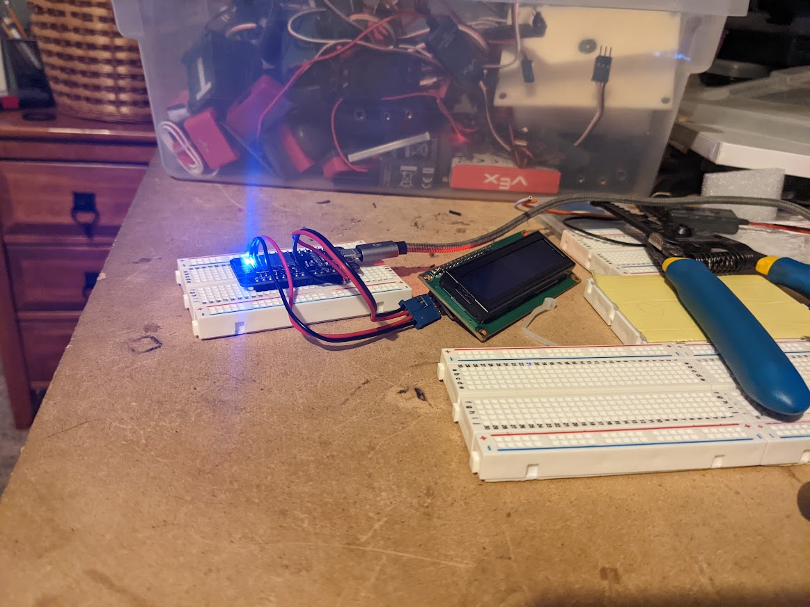
I started with simply figuring out how to program the silly thing with some breadboards and simple wires that I cannibalized from some old VEX electronics.
Here I am figuring out how to program some LED lights and the LCD. There’s an earlier revision of the back casing here too. I originally planned on making the device to be vertical in shape, but I realized that would be impractical to make it small enough, so I opted for a more simple design.
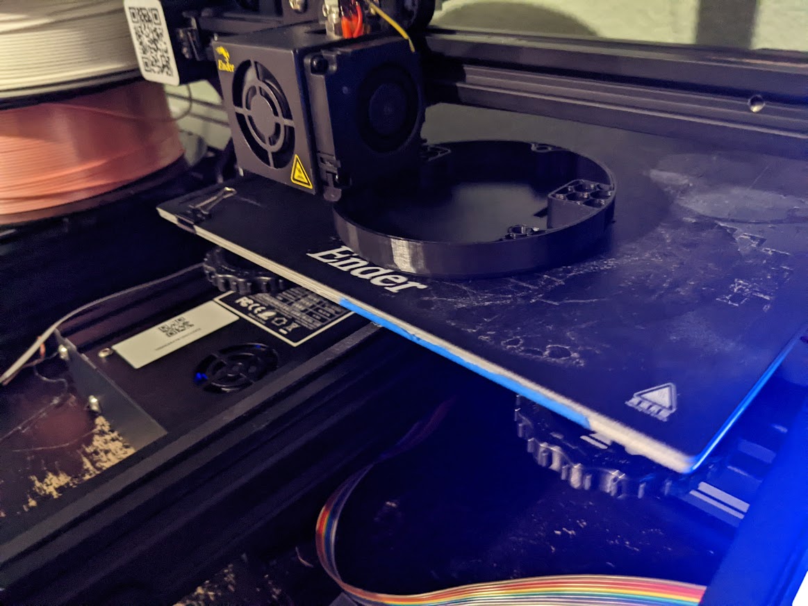
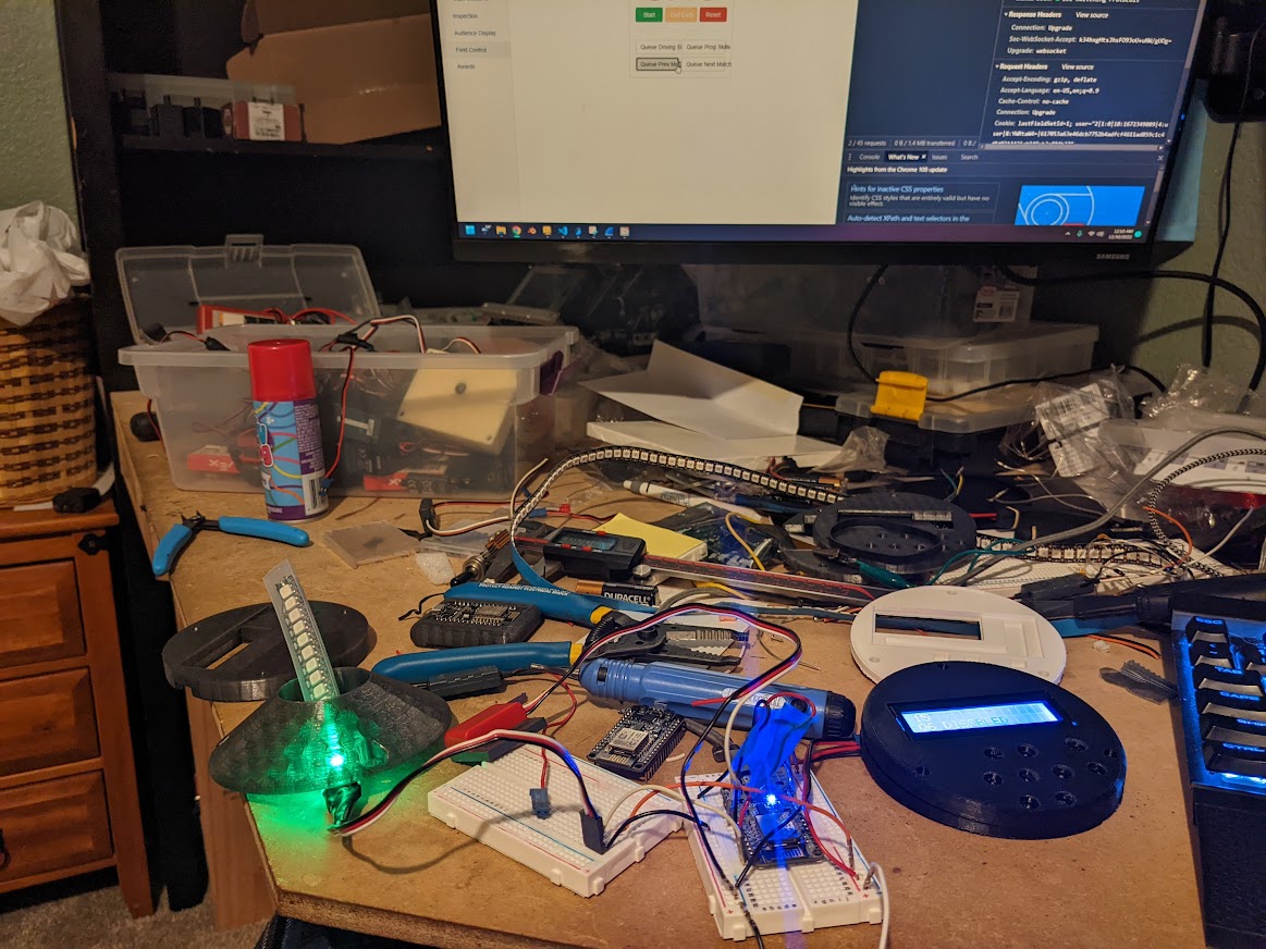
Here’s the final back shell printing. I was pleasantly surprised with how well my printer handled these parts, with complex overhangs and the like.
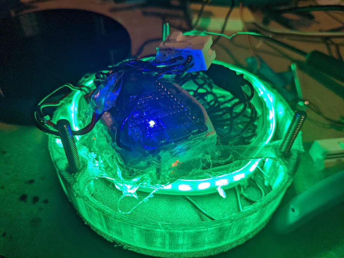
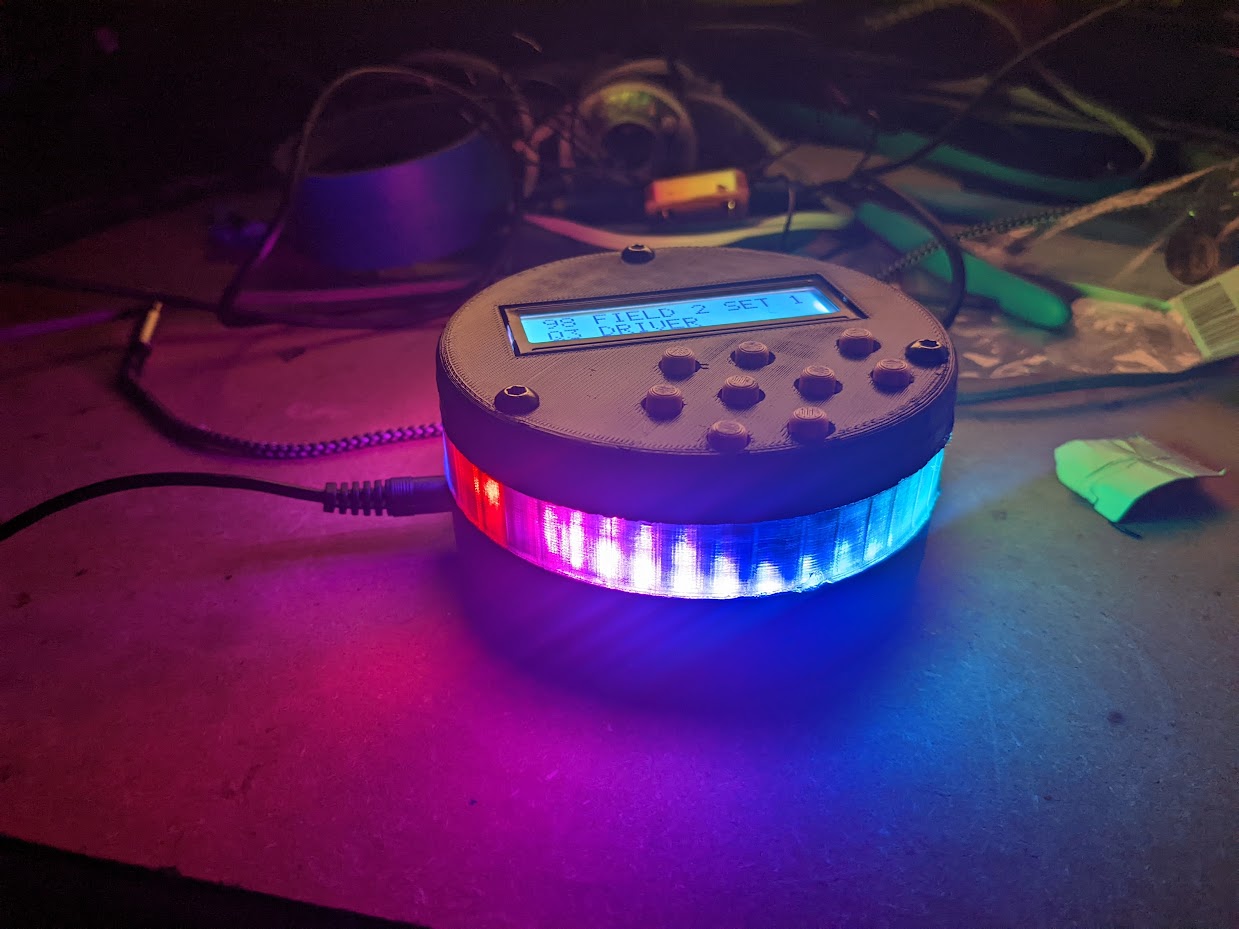
Once I got closer to having everything done, I assembled everything to see how it would look. The lights are very bright, and I think I like them a lot. For wiring the microcontroller, I decided to cut up a breadboard and hot-glue wires into it. This was an awful solution, but I didn’t have the patience to order any perfboards, and my soldering skills suck. It did work shockingly well though, I do have to say.
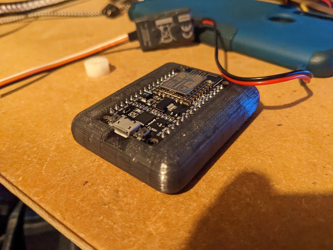
Originally I attempted to print a custom casing for the chip with holes for wires along the bottom, but it proved next to impossible to properly connect all of them.
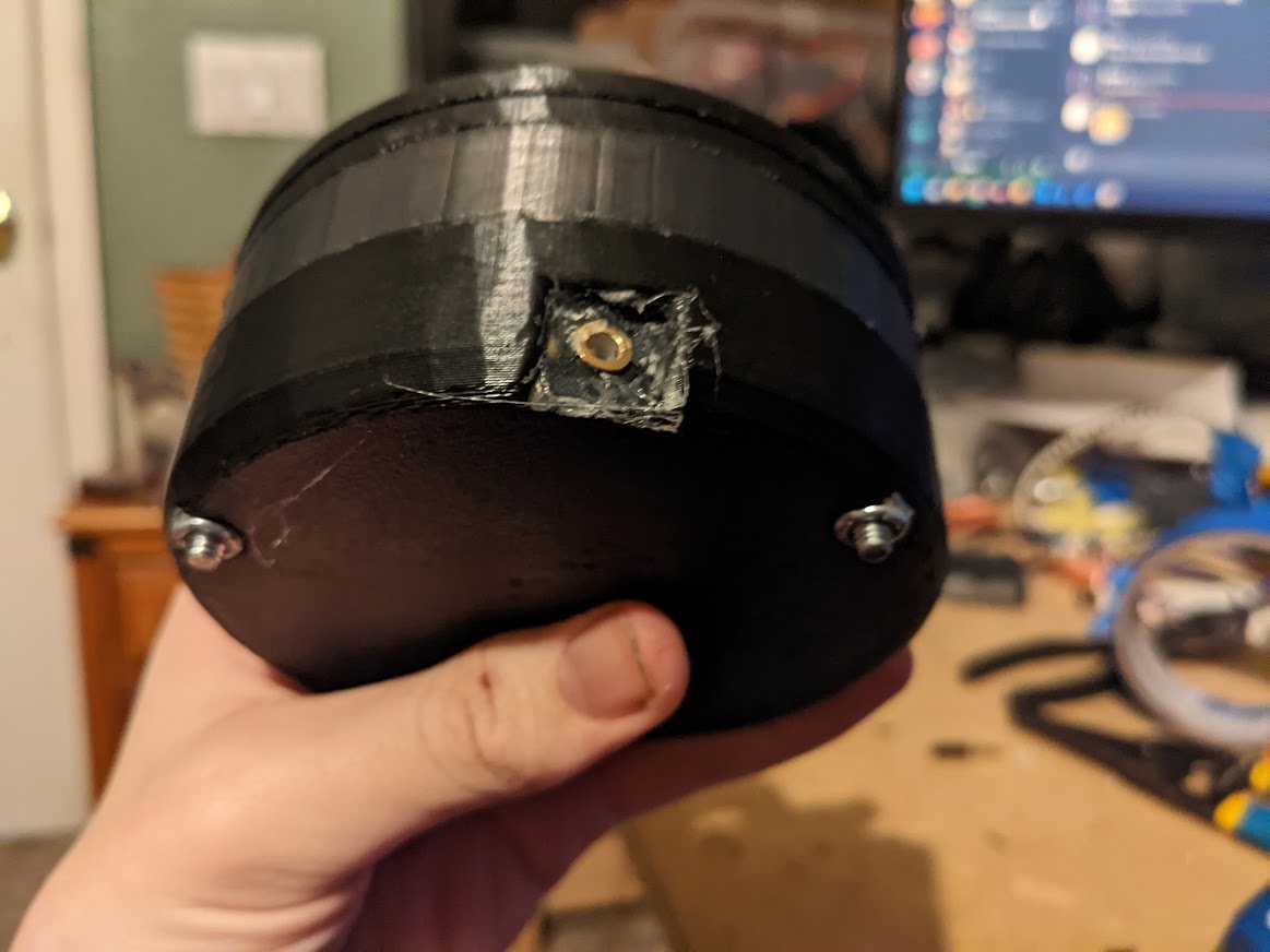
For the power supply, I ended up going with a 3.5mm jack for no good reason other than I thought it would be kinda funny. I cut up some old headphone cables and soldered the leads onto the wires connected to the power rails inside the device, and similarly to an old USB cable I had laying around. This way it can be powered with a simple USB battery pack or something similar. I considered buying a rechargeable battery and building it into the controller directly, but I realized I wouldn’t know what I was doing, and I didn’t want to risk doing anything dangerous.
All put together, it actually works fairly well. The two buttons on the right aren’t actually wired to anything, they’re just there so I would have something to fidget with while using the controller because that’s something I need for no good reason. I posted a video on my YouTube page to demonstrate it working.
I don’t expect this project to result in much - I doubt it will ever actually be used as intended, but it was still a fun project that taught me some embedded programming, electronics stuff, and how to go about designing something like this from scratch! ^_^